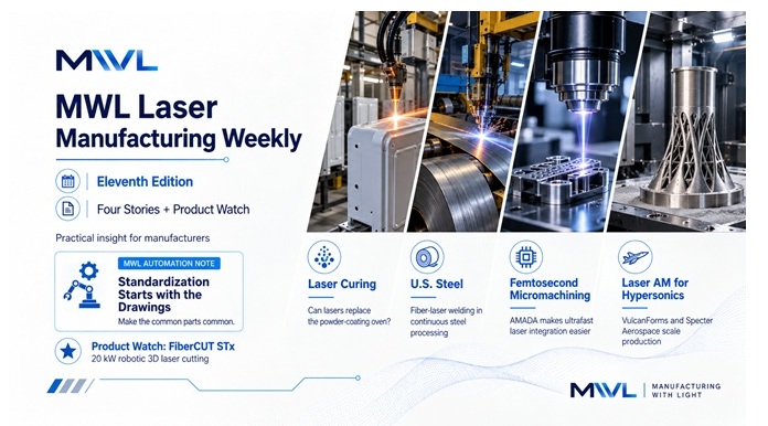
Four very different ways lasers are moving deeper into manufacturing
This week’s stories remind us that laser manufacturing goes far beyond cutting sheet metal and welding parts.
We start with an application that isn’t new, but I think it deserves another look: using laser energy instead of a conventional oven to cure powder coatings.
From there we move into continuous steel processing, femtosecond micromachining, and laser powder-bed fusion for hypersonic manufacturing.
In Product Watch, a new 20 kW robotic cutting head shows how high-power fiber lasers are continuing to move into heavy 3D cutting applications.
And in this week’s MWL Automation Note, we look at standardization—but with a slightly different starting point:
Maybe the programming standard shouldn’t start with the PLC program. Maybe it should start with the drawings.
In This Edition
- Worth Another Look: Can Lasers Replace the Powder-Coating Oven?
- U.S. Steel Installs a Fiber-Laser Welder at Great Lakes Works
- AMADA WELD TECH Makes Femtosecond Micromachining Easier to Integrate
- VulcanForms and Specter Aerospace Push Laser AM Toward Hypersonic Production
- Product Watch: Laser Mechanisms FiberCUT STx
- MWL Automation Note: Standardization Starts with the Drawings
1. Worth Another Look: Can Lasers Replace the Powder-Coating Oven?
This is not a new announcement. PPG, IPG Photonics, and Whirlpool first announced their collaboration in March.
But I think the application is unusual enough to warrant another look.
When we talk about industrial laser processing, cutting and welding usually come to mind first.
PPG, IPG Photonics and Whirlpool are exploring something very different: using laser energy to cure industrial powder coatings.
PPG installed an IPG PhotoniCURE laser-curing system on a pilot finishing line at its Strongsville, Ohio facility, along with a laboratory system near Pittsburgh. Whirlpool has been working with the companies to evaluate different powder formulations and appliance components. PPG Investor
Instead of heating the part in a conventional curing oven, the process uses targeted infrared energy to initiate the crosslinking reaction that transforms the powder into a durable coating.
PPG says the approach can cure coatings in minutes, reduce heat requirements and increase finishing-line throughput. It can be used with conventional powder chemistries as well as coatings formulated specifically for laser curing. PPG Investor
The collaboration also received the 2026 IRI Excellence Award for Open Innovation in June. PPG Investor
Why MWL readers should care
What I find interesting is that the laser is not replacing another laser process.
It is competing with a conventional manufacturing process.
If laser curing proves economically attractive at production scale, manufacturers could potentially rethink more than cure time.
This could affect oven size, factory floor space, energy consumption, thermal management, and finishing-line layout.
Some of the more interesting future opportunities for industrial lasers may come from manufacturing processes we don’t currently think of as laser processes at all.
PPG: Laser-based powder-curing collaboration
PPG: Laser Cure technology overview
2. U.S. Steel Installs a Fiber-Laser Welder at Great Lakes Works
Sometimes an important laser application is almost invisible inside a much larger manufacturing process.
U.S. Steel announced on September 29 that it had accepted delivery of a new fiber-optic laser beam welder for the pickle line at its Great Lakes Works facility in Ecorse, Michigan.
The equipment is part of a $28.3 million investment intended to increase the facility’s capability to produce advanced high-strength steel. U.S. Steel is also adding high-performance dual-pass entry shears as part of the upgrade. www.ussteel.com
The laser welder performs a very specific but important job.
As one steel coil reaches its end, the new system joins it to the beginning of the next coil, allowing material to continue through the processing line.
That may not sound as dramatic as welding an aircraft structure or an EV battery.
But on a continuous steel-processing line, that joint becomes part of the production infrastructure.
If it cannot be made quickly and reliably, the larger process is affected.
Why MWL readers should care
This is a good example of laser welding moving into heavy industrial production where uptime, automation, and process integration matter just as much as the weld itself.
The laser doesn’t directly create the final steel product.
It keeps the larger manufacturing process moving.
That means the successful laser system is much more than a laser source and welding head.
It has to become part of coil handling, material preparation, machine sequencing, controls, safety, diagnostics and the production process around it.
In other words:
The laser has to become part of the machine.
U.S. Steel: Great Lakes Works fiber-optic laser beam welder investment
3. AMADA WELD TECH Makes Femtosecond Micromachining Easier to Integrate
Femtosecond lasers can produce extremely precise features while minimizing many of the thermal effects associated with longer-pulse processes.
But creating a good femtosecond laser process and building a practical production machine around that process are two very different jobs.
AMADA WELD TECH has expanded its SIGMA LS Laser Micromachining Subsystem with a motorized beam-delivery head and new vertical and horizontal mounting options.
The goal is straightforward: make femtosecond laser processing easier for machine builders and system integrators to incorporate into production equipment and automated cells. AMADA WELD TECH
The subsystem packages the femtosecond laser, beam-delivery optics, scan or cutting head, focusing optics, camera, controller, and software into an integration-ready unit.
The new motorized-focus option lets you adjust the focal point through software rather than manually at the workpiece.
That can be useful for multi-level geometries, different material thicknesses and recipe-driven process changes. AMADA WELD TECH
Current SIGMA LS configurations offer femtosecond laser options from 5 W to 80 W, with IR, green and UV wavelength choices.
AMADA identifies applications including precision milling, selective ablation, drilling, surface texturing and scribing in materials including metals, polymers, ceramics and glass. AMADA WELD TECH
Why MWL readers should care
The interesting part of this story is not simply that another femtosecond laser exists.
It is the attempt to reduce the engineering required to turn an ultrafast laser process into a production machine.
A good process on an optical table is not yet a manufacturing system.
The final machine still needs beam delivery, motion or scanning, focus control, process parameters, vision, safety, contamination management, machine controls and serviceability.
Packaging more of those elements into a subsystem lets an OEM focus more engineering effort on the application.
That is another sign that ultrafast processing is continuing its transition from specialized laboratory technology into mainstream industrial equipment.
AMADA WELD TECH: SIGMA LS integration and motorized-focus upgrades
4. VulcanForms and Specter Aerospace Push Laser AM Toward Hypersonic Production
Metal additive manufacturing has spent years demonstrating that it can produce shapes that would be difficult—or sometimes impossible—to manufacture conventionally.
The harder question is increasingly:
Can we manufacture those parts repeatedly and economically at production scale?
Massachusetts-based VulcanForms and Specter Aerospace announced a strategic partnership on September 15 to scale U.S. manufacturing capacity for air-breathing hypersonic systems. VulcanForms
Specter says its development programs have already used VulcanForms’ 3D-printing and high-volume manufacturing capabilities.
The new agreement is intended to move that relationship from development toward larger-scale production. The companies are evaluating locations for a future dedicated manufacturing facility while using their existing production capabilities in the meantime. VulcanForms
The laser connection is substantial.
VulcanForms’ manufacturing platform combines laser powder-bed fusion, precision machining, automation, inspection, and software into an integrated production system.
Its GEN 3 LPBF platform uses a 40 kW laser system consisting of 75 individual 550 W lasers. VulcanForms
Why MWL readers should care
The interesting question here is no longer simply whether somebody can print an impressive aerospace component.
We know that can be done.
The harder question is whether laser powder-bed fusion can become one process within a reliable manufacturing system capable of sustained production.
Hypersonic hardware is a good candidate for additive manufacturing because thermal, aerodynamic, and structural requirements can create complicated geometries and internal passages.
But successful production requires much more than printing.
It requires machining.
Inspection.
Material and process traceability.
Automation.
Repeatability.
Quality control.
That is why I think this partnership is worth following.
Laser additive manufacturing continues to move from:
Can we print it?
toward:
Can we manufacture it reliably and at scale?
VulcanForms: Specter Aerospace hypersonic-manufacturing partnership
VulcanForms: GEN 3 laser powder-bed-fusion platform
Product Watch
Laser Mechanisms FiberCUT STx Brings 20 kW to Robotic 3D Laser Cutting
Laser Mechanisms has introduced the FiberCUT STx, a robotic laser cutting head designed to bring fiber-laser power levels up to 20 kW into three-dimensional cutting applications.
The STx builds on the company’s existing FiberCUT ST robotic cutting platform but significantly increases the available laser power.
Laser Mechanisms identifies target applications including:
- structural steel
- ultra-thick plate
- megacastings
- thick non-ferrous metals
The head is compatible with industrial robots rated at 25 kg and above and weighs approximately 6 kg.
Other specifications include fiber-laser wavelengths from 1030 to 1080 nm, assist-gas pressure up to 20 bar, and programmable focus-to-tip adjustment. Laser Mech
FABTECH 2026 lists the STx among its new products and describes it as designed and manufactured in the United States. Fabtech Expo
Why it caught our attention
Increasing laser power is only part of the challenge.
Making that power useful while a six-axis robot follows a complex three-dimensional path introduces another set of problems involving robot dynamics, path accuracy, standoff control, assist gas, focus position, and collision protection.
A compact 20 kW head that can operate on a conventional industrial robot could extend fiber-laser cutting into applications involving large castings, heavy fabrications, and complex 3D components.
That makes the FiberCUT STx interesting not simply as another cutting head, but as another example of high-power fiber lasers moving into manufacturing applications traditionally served by other cutting processes.
Laser Mechanisms: FiberCUT STx specifications
FABTECH 2026: FiberCUT STx new-product listing
MWL Automation Note
Standardization Starts with the Drawings
In the last Automation Note, I argued that working code and maintainable code are not always the same.
A machine can run perfectly well while its control program slowly accumulates inconsistent naming, one-off logic, outdated comments, commissioning modifications and those famous “temporary” fixes that somehow earn permanent residency.
One of the best ways to reduce that technical debt is standardization.
But I think there is an important point that often gets missed:
Standardization should not start with the PLC program. It should start with the engineering drawings.
Much of our control software ultimately exists to control physical devices.
Motors.
Valves.
Cylinders.
Sensors.
Drives.
Pressure switches.
Flowmeters.
Laser sources.
Chillers.
Gas systems.
Motion axes.
Most of those devices appear in the engineering documentation before the controls engineer writes the first rung of ladder logic or line of structured text.
The drawings should establish the machine’s vocabulary.
One Machine Should Not Have Five Names for the Same Device
Imagine an exhaust fan identified on the electrical drawing as:
EF-101
Then the PLC programmer calls it:
ExhaustFan_1
The HMI programmer calls it:
Fume Fan
The alarm says:
Dust Collector Blower Fault
And the maintenance manual calls it:
Main Extraction Fan
Technically, all five descriptions might be correct.
Practically, we have created a translation exercise for the technician standing next to a machine that is not running.
And that technician probably does not want a vocabulary lesson at 2:00 a.m.
A better approach is to establish a device identity during engineering and carry that identity through:
Drawings → Hardware → PLC/DCS → HMI → Alarms → Event History → Maintenance Documentation
The syntax doesn’t have to be identical.
A drawing package might use:
EF-101
while a PLC programming system requires:
EF_101
That is fine.
The important thing is that:
EF-101 still means EF-101 everywhere.
This is not just a personal preference. Established engineering standards also place strong emphasis on clear, consistent identification.
IEC 81346-14:2026, for example, addresses reference designations specifically for manufacturing and processing systems and describes their use for identifying and locating objects in the plant and in technical documentation. ISA-5.1 similarly establishes a uniform system for identifying instrumentation and control functions. IEC Webstore
Let the Drawings Become the Foundation
This changes how I think about a controls programming standard.
Instead of the controls engineer receiving the drawings and then inventing an entirely separate naming system, the drawings become part of the controls standard.
Device names, equipment descriptions, I/O descriptions and identifiers should be established early enough that they flow naturally into the software.
If the drawing identifies:
Shielding Gas Pressure — PT-201
the controls engineer should not then have to decide whether the PLC tag becomes:
GasPress1
Pressure_Input_7
or my personal favorite:
Tag_37
Tag_37 may run perfectly.
Six years later, however, troubleshooting it may require an archaeological permit.
Then Standardize the Software Around the Hardware
Once the machine’s vocabulary is established, software standardization becomes much more useful.
Common devices should behave in common ways.
A motor should have familiar:
- commands
- status
- permissives
- interlocks
- alarms
- manual controls
- diagnostics
A valve should follow a recognizable pattern.
Implementation can vary by control platform.
One system may use function blocks.
Another may use Add-On Instructions.
Another may use functions and structures.
The architecture matters less than the principle:
Make the common parts common.
The goal is not to make every machine identical.
Laser cutting, welding, cladding and additive-manufacturing systems can have very different process requirements.
Motion architectures differ.
Laser and motion synchronization differ.
Safety requirements differ.
Process sequencing differs.
Don’t force those things into an identical structure simply because somebody wrote a programming standard five years ago.
Standardize what really is common.
Then leave room for the engineering that makes the application unique.
Standardize the Troubleshooting Experience Too
The same philosophy should carry over to the HMI.
If a device cannot start because three permissives are missing, show the technician the missing permissives.
If an interlock stopped the machine, identify the interlock.
If a sequence is waiting for something, show what it is waiting for.
The alarm should also include the device identity shown on the drawing.
Compare:
ALARM 327 — DEVICE FAULT
with:
EF-101 Exhaust Fan — VFD Fault — Verify Drive Ready
One of those gives the technician somewhere to start.
The other gives them a number.
IEC 62682 provides a useful formal framework for alarm management and emphasizes alarms that support operator response to abnormal process conditions and equipment malfunctions. IEC Webstore
Standards Can Become Technical Debt Too
There is one more problem.
A company creates a programming standard.
Everyone celebrates.
The document goes into a folder.
Five years later, the controls platform has changed twice, several programmers have added their own improvements, and nobody is entirely sure which version is actually the standard.
Congratulations.
We have standardized our inconsistency.
Drawing templates, reusable software modules, HMI objects, device definitions and alarm conventions need revision control just like production software.
A standard should be something we maintain.
Not something we wrote once.
And Eventually, AI Will Care Too
There is a lot of discussion about AI eventually helping technicians troubleshoot industrial equipment.
Maybe it will.
But an AI system will face exactly the same fundamental problem a technician does if the machine information is inconsistent.
If the electrical drawing says:
EF-101
the PLC says:
ExhaustFan_1
the HMI says:
Fume Fan
and the historian says:
Blower 3
Software first has to determine whether those are four different devices or one.
Consistent device identities, meaningful alarms, documented machine states and useful event histories help technicians today.
They will also make machine information much more useful to future diagnostic tools.
Preparing a machine for AI may therefore begin with something considerably less glamorous than artificial intelligence:
Good drawings and good tag names.
The goal of standardization is not to make every machine identical.
It is to establish a common engineering language from the drawings through the control system and all the way to maintenance.
Standardize the boring parts so engineers can spend their time engineering the interesting parts.
Automation Note References
IEC 81346-14:2026 — Reference designations for manufacturing and processing systems
ISA-5.1 — Instrumentation and Control Symbols and Identification
IEC 62682:2022 — Management of alarm systems for the process industries
From the Shop Floor
Some of the most useful manufacturing lessons never make it into formal technical papers.
They start with:
“We thought this would be easy…”
MWL is looking for practical experiences from people who build, operate, maintain and improve laser manufacturing systems.
If you have learned something worth sharing about laser cutting, welding, cleaning, micromachining, additive manufacturing, motion control, automation, maintenance or process development, I would like to hear about it.
It does not need to be a polished article.
The important part is the lesson.
Consultants Corner
Are you an independent consultant working in laser processing, materials, automation, controls, safety, additive manufacturing or another field connected to Manufacturing With Light?
MWL welcomes contributed technical articles that provide useful information for our readers while also giving experienced specialists an opportunity to introduce their expertise to the manufacturing community.
Manufacturing With Light Weekly
Practical information about how lasers are being used to make things—and the machines, processes, and people that make those applications work.
If you find MWL useful, please subscribe and share Edition 11 with someone working in laser manufacturing.