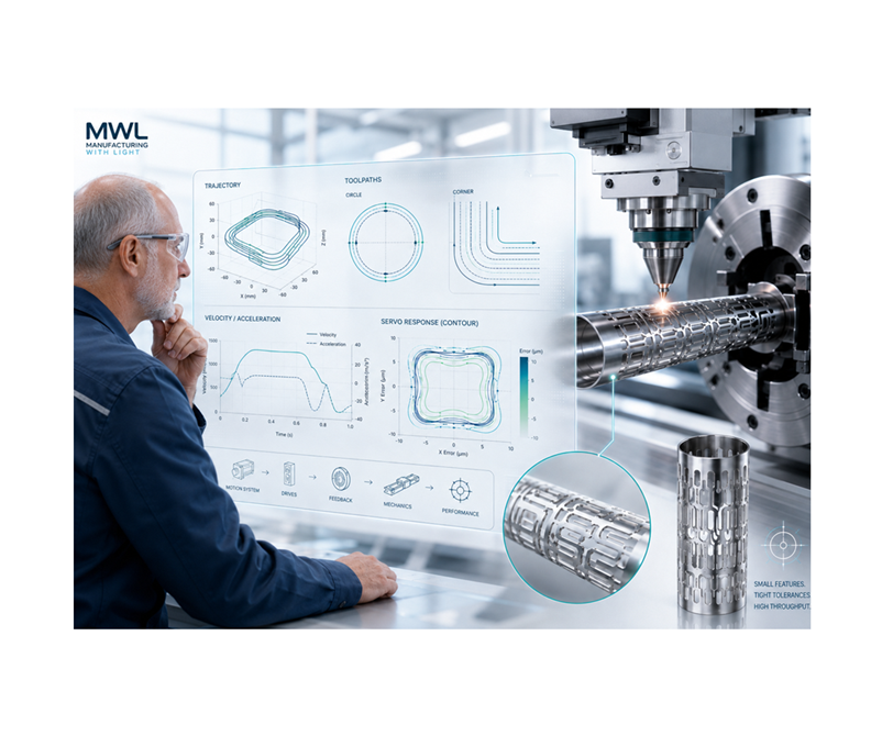
When people begin sizing a motion system for a laser-cutting machine, the conversation often starts with familiar numbers:
- How much travel is required?
- How fast must the machine move?
- What size motor should we use?
- What is the maximum rapid-traverse speed?
- How many watts does the motor produce?
Those questions matter, but they do not tell the whole story when the machine must cut small features at high production rates.
A motion system can move very quickly across a large work area and still struggle to cut a small hole, a tight inside radius, or a series of short line segments.
The more important question is:
Can the machine accurately follow the smallest feature at the required production speed?
Small circles and frequent changes in direction are among the most demanding trajectories for a servo-controlled motion system. The axes must continuously accelerate, decelerate, and reverse direction while remaining synchronized. Dynamic tracking error normally becomes most noticeable around these reversals, even when the machine’s static positioning accuracy looks excellent.[1] (Aerotech US)
Start with the smallest feature, not the longest move
Imagine that a machine must cut a very small circular feature.
The laser may only be moving at what appears to be a reasonable cutting speed. However, the X and Y axes are continuously changing direction as they generate the circle.
As the circle gets smaller, the required acceleration increases. If we also increase the cutting speed to improve throughput, the motion becomes much more demanding.
The basic relationship for circular motion is:
[
\omega=\frac{v}{r}
]
Where:
- (v) is the cutting speed
- (r) is the radius of the feature
- (\omega) is the rate at which the direction of motion changes
For readers who are not engineers, the important point is simple: the same cutting speed becomes harder to control as the feature gets smaller.
The frequency of one complete trip around the circle can be calculated as:
[
f_{\text{path}}=\frac{v}{2\pi r}
]
This path frequency gives us an idea of how quickly the X and Y axes must repeatedly change direction.
The acceleration required to remain on the circular path is:
[
a_n=\frac{v^2}{r}
]
Notice that velocity is squared.
That means doubling the cutting speed does not merely double the required acceleration. It increases it by a factor of four.
The approximate jerk requirement is:
[
j=\frac{v^3}{r^2}
]
Jerk is the rate at which acceleration changes. It is important because very abrupt changes in acceleration can excite the machine structure, create vibration, and increase contour error.
In plain language:
- Smaller features demand more acceleration.
- Higher speed demands much more acceleration.
- Combining small features with higher throughput can increase the motion requirements very quickly.
A simple example
Suppose the system must cut a radius of 0.10 millimeter at a cutting speed of 50 millimeters per second.
That produces approximately:
- A path frequency of 79.6 hertz
- An acceleration of 25 meters per second squared
- An acceleration level of about 2.5 g
- A jerk requirement of approximately 12,500 meters per second cubed
A 5-kilogram moving assembly would require approximately 125 newtons of force simply to produce that acceleration:
[
F=ma
]
Where:
- (F) is force
- (m) is moving mass
- (a) is acceleration
That 125-newton calculation does not yet include friction, cable forces, gas hoses, bearing losses, disturbances, or design margin.
Now reduce the cutting speed by half.
The acceleration requirement falls by a factor of four, and the jerk requirement falls by a factor of eight.
This explains why slowing down around a small feature can dramatically improve quality—but it can also reduce the throughput the customer expected to receive.
A made-up story to illustrate the problem
The following story is fictional. It is only being used to make a point.
Imagine a machine builder developing a new laser cutter. The customer asks for high throughput, so the builder selects a motion system with an impressive maximum velocity and large motors.
During initial testing, the machine moves rapidly across the work area. Long straight cuts look good, and the system easily passes the rapid-traverse test.
Then the customer supplies the actual production part.
The part contains dozens of small holes and narrow slots. At the desired cutting speed, some of the holes become slightly oval, the slot corners are rounded, and the kerf changes around tight turns.
The machine builder reduces the cutting speed, and the features improve—but the cycle time is no longer acceptable.
Everyone initially assumes that the motors are too small.
After more testing, the team discovers that motor force is only one part of the problem. The cutting head and cable carrier create more moving mass than expected. A mechanical resonance limits servo bandwidth. The two axes do not track identically during direction changes, and the laser continues depositing energy while the machine slows around corners.
The machine had plenty of top speed.
What it lacked was sufficient dynamic path performance at the smallest feature.
Moving mass includes more than the carriage
Motor sizing normally begins with the complete motion profile and the total moving mass. Parker’s linear-motor sizing guidance recommends including the motor components, user payload, and all other moving items before calculating peak force, RMS force, current, voltage, and motor temperature.[2] (Parker Hannifin Corporation)
On a laser-cutting machine, moving mass may include:
- The laser-processing head
- Focusing optics
- Nozzle and height sensor
- Assist-gas hoses
- Fiber routing
- Cable carrier
- Covers and bellows
- Upper stages carried by lower stages
- Workpiece and fixture, when the part moves
Cable carriers and hoses can also produce position-dependent forces. The axis may behave differently near one end of travel than it does near the center.
A larger motor can provide more force, but installing the largest available motor is not always the answer. A larger motor may add moving mass or rotary inertia, increase heat, require a larger drive, and make the mechanical system harder to tune.
Motor selection is usually an iterative process.
Peak force is not enough
The motor and drive must satisfy both peak and continuous requirements.
Peak force determines whether the axis can produce the required acceleration. RMS force helps determine whether the motor can repeat the complete production cycle without overheating.
A simplified RMS-force calculation is:
[
F_{\text{RMS}}=
\sqrt{\frac{F_1^2t_1+F_2^2t_2+\cdots+F_n^2t_n}
{t_1+t_2+\cdots+t_n}}
]
For non-engineers, RMS force can be thought of as the motor’s effective workload over the entire cycle.
A motor may be capable of producing a high force for a short time but may not be able to repeat that motion continuously without exceeding its thermal limit.
The drive also needs enough:
- Peak current
- Continuous current
- Voltage at maximum speed
- Overload duration
- Regenerative-energy capacity
The calculation must reflect the actual production path—not just one acceleration move performed during commissioning.
Positioning accuracy is not path accuracy
Static positioning accuracy tells us how closely an axis can reach a commanded position.
That is useful, but it does not tell us how accurately two axes will follow a small contour while moving at production speed.
A machine might position accurately at the end of every move and still produce:
- Oversized or undersized holes
- Oval circles
- Rounded corners
- Uneven slot widths
- Local changes in kerf
- Small marks where velocity changes
For small-feature cutting, the important measurement is the vector contour error at the laser spot.
This includes the combined effects of both axes, the mechanical structure, the encoders, the servo response, machine geometry, thermal drift, workholding, and the distance between the measurement point and the actual laser work point.
Aerotech’s public contour-control material specifically identifies small-circle motion and axis direction reversals as difficult tracking conditions. Its examples also show that improved tracking control can reduce dynamic contour error even when the basic mechanics remain unchanged.[1] (Aerotech US)
Servo tuning matters, but mechanics come first
The motor, encoder, drive, bearings, frame, cable system, and controller must work as one system.
A good servo tune can improve tracking, disturbance rejection, and settling performance. It cannot completely compensate for:
- A flexible frame
- Loose mechanical connections
- Poor bearing selection
- Excessive cable forces
- Low-frequency structural resonance
- An oversized moving assembly
- Poor alignment between the axes
The motion system should be tested using frequency-response tools with the final payload, laser head, cables, hoses, and covers installed.
The machine may tune well when the stage is empty and behave very differently after all production hardware is added.
Advanced motion-profile generation can also reduce the disturbances introduced by the commanded trajectory. ACS describes trajectory generation as a major factor in both throughput and accuracy because poorly constructed profiles can excite vibration and increase dynamic following error.[3] (ACS Motion Control)
The controller and trajectory generator are part of the sizing process
A small feature is not only a motor-and-drive problem.
The controller must create and deliver a sufficiently smooth trajectory.
When a circle or curve is represented by many short straight lines, there will be some difference between the intended curve and the generated path. The approximate chord error is:
[
e_{\text{chord}}\approx\frac{v^2}{8rf_t^2}
]
Where:
- (e_{\text{chord}}) is the geometric path error
- (v) is path velocity
- (r) is feature radius
- (f_t) is the trajectory-point rate
Rearranging the equation gives an estimate of the required point rate:
[
f_t\geq\frac{v}{\sqrt{8re_{\text{allow}}}}
]
The non-engineering explanation is that a curved path can look like a polygon if the controller receives too few points. Increasing the number of points makes the path smoother, but it also increases the amount of data the controller must process.
Native arcs, splines, NURBS, segmented motion, and smoothing algorithms can help. ACS, for example, describes SmoothPath as an advanced coordinated contour algorithm intended to maintain process speed while reducing disturbances from discontinuities in CAD- or CAM-generated paths.[4] (ACS Motion Control)
ACS also publishes G-code support for laser-processing applications using segmented motion or SmoothPath, with processing rates stated at up to 5,000 blocks per second.[5] (ACS Motion Control)
The correct controller rate cannot be selected from the smallest feature alone. It must also account for servo bandwidth, path construction, communication architecture, look-ahead, filtering, and the amount of acceptable contour error.
Laser timing must follow the motion
Even a well-sized motion system can produce inconsistent features if the laser output is not correctly synchronized with the trajectory.
For a pulsed laser, the nominal distance between pulses is:
[
s=\frac{v}{f_L}
]
Where:
- (s) is pulse spacing
- (v) is cutting speed
- (f_L) is laser repetition frequency
If the laser fires at a constant time interval while the machine slows for a corner, the pulses become more closely spaced.
That can increase local energy density and affect:
- Kerf width
- Heat input
- Edge quality
- Material removal
- Heat-affected zone
- Feature size
Position-synchronized firing triggers the laser according to distance traveled rather than elapsed time. Aerotech describes fixed-distance position-synchronized output as a way to avoid pulse-placement errors caused by acceleration, deceleration, and velocity instability.[6] (Aerotech US)
ACS’s Laser Control Interface similarly supports fixed-distance pulsing, segment-based gating, coordinate-array modes, multi-axis triggering, and velocity-based power control.[7] (ACS Motion Control)
Timing uncertainty can also be converted into a position error:
[
e_{\text{timing}}=v,t_{\text{latency}}
]
At a cutting speed of 100 millimeters per second, one microsecond of timing uncertainty corresponds to 0.1 micrometer of travel.
That may sound extremely small, but the effect becomes more important as processing speed increases and feature tolerances become tighter.
Sometimes the correct architecture is not a larger stage
For moderate speeds and less demanding features, a ballscrew-driven stage may be completely appropriate.
For frequent reversals and higher acceleration, a direct-drive linear motor may offer advantages because it eliminates the screw, coupling, and mechanical transmission.
For extremely small, high-speed local features, a galvanometer scanner may provide better dynamics because only lightweight mirrors are moving.
A synchronized stage-and-scanner system can divide the work:
- The mechanical stage handles the long travel and lower-frequency motion.
- The scanner handles the short, high-frequency feature content.
PI describes coordinated stage-and-scanner systems as a method of processing larger areas without relying on separate tiled fields, while retaining a smaller optical field and spot size.[8] (Physik Instrumente)
The right architecture depends on feature size, work area, optical requirements, payload, accuracy, process speed, and cost.
How should the motion system be sized?
A practical sequence is:
- Identify the smallest radius, hole, slot, and line segment.
- Establish the required cutting speed through those features.
- Calculate path frequency, acceleration, jerk, and motor force.
- Include every moving component in the mass and inertia calculation.
- Calculate peak and RMS motor requirements over the complete cycle.
- Define allowable dynamic contour error at the laser spot.
- Evaluate structural stiffness and mechanical resonance.
- Verify controller trajectory generation and processing rates.
- Determine how laser pulses, gates, and power will follow velocity and position.
- Test the actual feature at production speed.
Acceptance testing should include the smallest feature, the highest-throughput path, the final payload, and the real cable and hose arrangement.
Do not rely only on:
- Maximum rapid-traverse speed
- Static repeatability
- Point-to-point positioning
- Motor nameplate power
- A large circle cut at a reduced speed
The main takeaway
When small features and throughput matter, the motion system should be sized around the most demanding part of the cutting path.
That is usually not the longest move or the maximum straight-line speed.
It is more likely to be:
- The smallest radius
- The shortest segment
- The fastest direction reversal
- The highest required acceleration
- The most demanding combination of contour accuracy and laser timing
The goal is not simply to build a machine that moves fast.
The goal is to build a machine that can cut the required feature accurately, consistently, and repeatedly—at the production speed the customer expects.
References
[1] Aerotech, Enhanced Tracking Control—Improvements in Dynamic Tracking
[2] Parker Hannifin, Linear Motor Sizing Application Note
[3] ACS Motion Control, Motion Profile Generation
[4] ACS Motion Control, SmoothPath
[5] ACS Motion Control, G-Code Programming for Laser Processing and CNC Machines
[6] Aerotech, Position Synchronized Output—Coordinate Position with Process Control
[7] ACS Motion Control, LCI Laser Control Interface
[8] Physik Instrumente, Motion Systems for Laser Material Processing
The organization of the ACS motion and laser-control sections also follows the laser-processing training material supplied for this project.
Disclosure: AI tools were used to assist with the research, organization, and drafting of this article. The final content was reviewed and edited by the author, who remains responsible for its accuracy and conclusions.