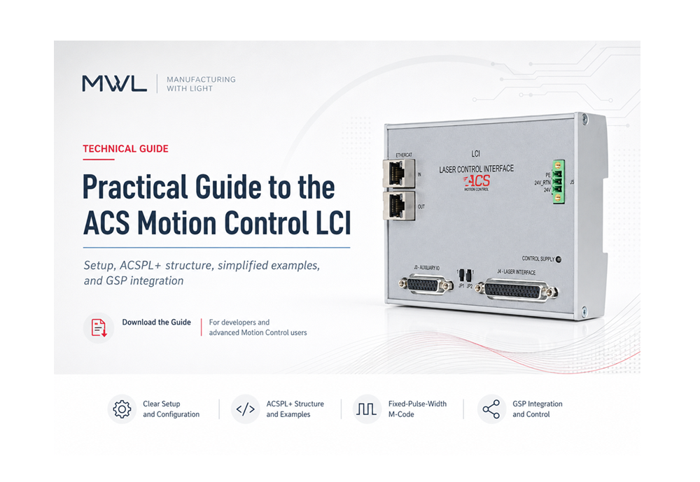
Setup, ACSPL+ structure, simplified examples, GSP integration, and a robust fixed-pulse-width M-code
For current ACS Motion Control users with programming experience
| Initialize the LCI and establish a repeatable startup sequence |
| Understand the most useful structure fields and operating modes |
| Use PWM, fixed-distance pulsing, and segment gating |
| Expose LCI functions to G-code with simulator, dry-run, and error handling |
Prepared by William Kane
Manufacturing with Light (MWL)
Document revision 1.0 | July 2026
Independent technical guide based on ACS Motion Control documentation. This guide is not a substitute for the current manuals, application-specific validation, or a properly engineered laser safety system.
About this guide
The ACS Motion Control Laser Control Interface (LCI) can place laser timing inside the same real-time control environment that generates the machine trajectory. The result is a practical way to coordinate laser pulses, gates, and power-related outputs with time, position, velocity, or motion segments. The LCI is an EtherCAT slave and is programmed through an ACSPL+ standard structure. [1][2][3]
This guide is organized as a commissioning path rather than a command catalog. It begins with hardware and initialization, explains the structure and common modes, then builds toward G-code integration and a custom M-code with validation and fault reporting.
| Important safety boundaryLCI software is process control, not a safety-rated laser controller. Initial tests should be performed with the laser source disabled or disconnected, using appropriate test equipment. Do not mask the L_FLT or LCS_EN inputs in production unless the complete machine risk assessment explicitly permits it. [1][2] |
Contents
- 1. What the LCI does
- 2. Hardware, EtherCAT, and safety setup
- 3. Declaring and initializing the LCI structure
- 4. Important fields and the operating lifecycle
- 5. Simplified PWM, fixed-distance, and segment-gate examples
- 6. Integrating LCI functions into G-code through GSP
- 7. Simulator and dry-run strategy
- 8. Robust M501.2 fixed-pulse-width example
- 9. Commissioning checklist and references
Scope and assumptions
The examples assume one LCI named lc, axes X and Y when vector motion is needed, and a GSP project that already provides the user variables FREQ, LPWH, MINVAL, MAXVAL, MINVEL, MAXVEL, and DRY_RUN. Those names are application-specific. The LCI functions and fields shown in this guide are documented in ACS revision 4.20/4.20.01 manuals. [1][3]
1. What the LCI does
The LCI tightly synchronizes a fixed-beam laser with an ACS SPiiPlus motion trajectory. The module can base its output on time, path position, vector velocity, or the start of individual motion segments. ACS describes support for synchronization with multi-axis paths, including 2D, 3D, and 5D applications. [2][5]
Three useful ways to think about the LCI
| Control basis | Practical meaning |
|---|---|
| Time based | Generate a pulse train with a selected frequency, pulse width, or duty cycle. One parameter can vary with velocity in modes 1-3. |
| Position based | Generate pulses at fixed spatial intervals or at positions held in arrays. This is useful when constant pulse spacing matters more than constant frequency. |
| Segment based | Use the /p value on LINE, ARC, SEGMENT, and related commands to switch a gate or issue a pulse at the beginning of selected path segments. |
These modes can be combined. A common laser-cutting pattern is to use PWM to define the pulse train and segment gating to define where that train is allowed to reach the laser interface. [1][3]
The programming object
The LCI is exposed as a firmware-defined ACSPL+ standard structure. The application declares an object and then calls functions or reads fields with dot notation. [3][4]
Basic object-style workflow
global LCI lc
lc.Init()
lc.SetMotionAxes(X,Y)
lc.PowerPWMOut(0,50000,0.004,0)
lc.LaserEnable()
! Execute motion or process sequence
lc.LaserDisable()
lc.Stop()
2. Hardware, EtherCAT, and safety setup
The LCI is a DIN-rail EtherCAT slave. The current installation guide identifies five primary connectors. [2]
| Connector | Assignment | What to verify |
|---|---|---|
| J1 | EtherCAT In | Correct network order and cable |
| J2 | EtherCAT Out | Next slave or unused |
| J3 | Auxiliary I/O | Configurable outputs and general I/O |
| J4 | Laser interface | Signal format, polarity, voltage, and timing |
| J5 | 24 V control supply | 24 VDC, return, and protective earth |
Wiring points that deserve attention
- The installation guide calls for CAT5e EtherCAT cable, 18 AWG logic-power wiring, and a 24 AWG 120-ohm twisted pair for the laser connection. [2]
- Recommended maximum lengths are 3 m for logic power, 10 m for the laser connection and digital I/O, and 50 m per EtherCAT link. [2]
- The LCS_D interface can use the LCI internal supply and supports differential or single-ended signaling; the selected interface must match the laser control input. [2]
Safety inputs and restart behavior
The dedicated L_FLT and LCS_EN inputs are used for laser fault and external safety permission. During a safety event, the guide states that pulse generation stops and laser-related, configurable, analog, and general-purpose outputs return to their default states. Jumper JP1 sets sink/source connectivity for the digital inputs. [1][2]
Safety mask syntax
! Development only – masks both safety-related inputs
lc.SetSafetyMasks(1,1)
! Normal production intent – use the inputs
lc.SetSafetyMasks(0,0)
| Revision 4.20 initialization noteAfter an L_FLT or LCS_EN event is cleared, run lc.Init() before resuming the application. The June 2026 LCI application note added this instruction explicitly. [1] |
EtherCAT health check
Before an M-code attempts to address the LCI, the application can verify that the EtherCAT bus is operational. The Programmer’s Guide states that monitoring ECST.#OP is sufficient for the overall bus state; a bus error resets that bit. [4]
Optional application-level bus check
IF ^ECST.#OP
DISP “LCI ERROR: EtherCAT bus is not operational”
! Set application alarm and exit
END
3. Declaring and initializing the LCI structure
Declare the object in the D-buffer
The D-buffer is the normal location for global objects that must be visible to GSP extension routines and regular ACSPL+ buffers. The D-buffer is compiled before the other buffers, and all dependent buffers should be recompiled after it changes. [4]
D-buffer declaration
global LCI lc
Initialize before configuring a mode
The examples in the LCI manuals use lc.Init() to set the LCI to its default state before assigning axes and defining an operation. Initialization also resets pulse counters and previously configured state. Apply project-specific fields after the call. [1][3]
Repeatable startup routine
LCI_INIT:
lc.Init()
lc.SetMotionAxes(X,Y)
lc.PosResolution = 0
lc.SetSafetyMasks(0,0)
RET
| Avoid accidental reinitializationBecause lc.Init() returns the structure to default state, do not hide it inside a frequently called helper unless resetting all LCI modes is intentional. A common architecture initializes once, then uses separate M-codes to configure, enable, disable, and stop the process. |
Select the motion axes
SetMotionAxes defines the logical X/Y/Z/A/B/C axes used by subsequent laser operations. The manual accepts one axis or an axis group with valid platform codes 0 through 5. Direct assignment to MotionAxes with AxListAsMask is also documented. [1][3]
Two supported styles
lc.SetMotionAxes(X,Y)
! Equivalent mask-style assignment
lc.MotionAxes = AxListAsMask(X,Y)
Let the firmware calculate resolution first
PosResolution is writable. When it is zero, the firmware calculates the pulse resolution from the velocity limits and the maximum LCI frequency, and reports the actual result in InternalPosResolution(channel). When a value is forced manually, the application becomes responsible for the related maximum-speed and frequency restrictions. [1][3]
4. Important fields and the operating lifecycle
Fields worth monitoring
| Field | Access | Use |
|---|---|---|
| MotionAxes | R/W | Default axes mask for LCI trajectory calculations |
| PosResolution | R/W | Requested pulse resolution; zero enables calculation |
| InternalPosResolution(channel) | Read only | Actual resolution used by the selected channel |
| PWMFrequency | Read only | Current frequency in hertz |
| PWMPulseWidth | Read only | Current pulse width in milliseconds |
| PWMActive | Read only | 1 when modulation mode is active |
| LaserEnabled | Read only | 1 when laser generation is enabled |
| OperationMode(channel) | Read only | Operation assigned to the channel |
| Positions(channel) | Read only | Internal channel position/count value |
| UserPos(channel) | Read only | Channel position in user units |
| Faults | Read only | Current LCI error state |
A reliable lifecycle
- Initialize and establish common settings.
- Select the motion axes and resolution policy.
- Configure a pulse, modulation, or gating operation.
- Validate parameters and check the returned channel/status fields.
- Enable laser generation only when the machine is ready.
- Execute the motion or G-code path.
- Disable generation, then stop the active LCI operations.
LaserDisable() prevents pulse generation. Stop(channel) cancels the specified operation; omitting the channel or passing a negative value cancels all active operations. A conservative shutdown uses both functions. [3]
Conservative stop sequence
lc.LaserDisable()
lc.Stop()
5. Simplified programming examples
Example 1: fixed-frequency, fixed-width PWM
PowerPWMOut initializes pulse modulation. Frequency is specified in hertz and pulse width in milliseconds. Mode 0 uses fixed parameters; the duty-cycle argument is not applicable. [1][3]
50 kHz, 4 microsecond pulse
global LCI lc
PWM_TEST:
lc.Init()
lc.PowerPWMOut(0,50000,0.004,0)
IF ^lc.PWMActive
DISP “PWM configuration did not become active”
lc.Stop()
STOP
END
DISP “Frequency Hz =”, lc.PWMFrequency
DISP “Pulse width ms =”, lc.PWMPulseWidth
lc.LaserEnable()
STOP
PWM_TEST_OFF:
lc.LaserDisable()
lc.Stop()
STOP
The manuals recommend this type of static PWM test for initial debugging because no axis motion is required. Confirm the signal with appropriate instrumentation while the laser source is disabled or disconnected. [1]
Understanding the four PowerPWMOut modes
| Mode | Name | Practical behavior |
|---|---|---|
| 0 | Fixed parameters | Frequency and pulse width remain fixed |
| 1 | Fixed frequency | Duty cycle can vary with vector velocity |
| 2 | Fixed pulse width | Frequency can vary with vector velocity |
| 3 | Fixed duty cycle | The variable parameter is controlled by the documented mode behavior |
The documented frequency range is 0.035 Hz to 1 MHz. The documented pulse-width range is 6.67 ns to 28.60 s, but the argument is always entered in milliseconds. In mode 2, DutyCycle has no effect because the LCI calculates it from frequency and width. [1][3]
Example 2: fixed pulse width with velocity-based frequency
10-50 kHz while velocity changes from 10-100 user units/s
int Mode = 2
real InitialFreq = 10000
real PulseWidth = 0.004
real DutyCycle = 0
real MinFreq = 10000
real MaxFreq = 50000
real MinVelocity = 10
real MaxVelocity = 100
lc.Init()
lc.SetMotionAxes(X,Y)
lc.PowerPWMOut(Mode,InitialFreq,PulseWidth,DutyCycle,MinFreq,MaxFreq,MinVelocity,MaxVelocity)
IF lc.Faults <> 0 | ^lc.PWMActive
DISP “LCI PWM configuration failed; faults =”, lc.Faults
lc.LaserDisable()
lc.Stop()
END
In mode 2, MinValue and MaxValue are frequency values. They must be passed to PowerPWMOut in hertz even when the G-code interface presents them to the operator in kilohertz.
Example 3: fixed-distance pulsing
FixedDistPulse fires at equal spatial intervals along the actual multi-axis path. The return value is the occupied channel index. Pulse width is in milliseconds; interval, start, end, and offset values are in controller user units. [1][3]
10 microsecond pulse every 0.10 user unit
int PulseChannel
int PulseCount
lc.Init()
lc.SetMotionAxes(X,Y)
PulseChannel = lc.FixedDistPulse(0.01,0.10)
IF PulseChannel < 0
DISP “Fixed-distance channel allocation failed”
lc.Stop()
STOP
END
lc.LaserEnable()
PTP/e (X,Y),100,0
lc.LaserDisable()
PulseCount = lc.GetPulseCounts(PulseChannel)
DISP “Generated pulse count =”, PulseCount
lc.Stop()
GetPulseCounts returns the internal counter for a channel. The count resets when a new operation is defined or when lc.Init() or lc.Stop() is called. [1][3]
Example 4: segment gating
SegmentGate allocates a channel and lets the /p parameter set gate state at the beginning of each motion segment. The function returns -1 if allocation fails. [3][4]
PWM defines the waveform; /p defines where it is passed
int GateChannel
lc.Init()
lc.SetMotionAxes(X,Y)
GateChannel = lc.SegmentGate(0)
IF GateChannel < 0
DISP “Segment gate initialization failed”
lc.Stop()
STOP
END
lc.PowerPWMOut(0,50000,0.004,0)
lc.LaserEnable()
XSEG (X,Y),0,0
LINE/p (X,Y),10,0,0 ! approach – gate off
LINE/p (X,Y),40,0,1 ! process – gate on
LINE/p (X,Y),50,0,0 ! exit – gate off
ENDS (X,Y)
TILL GSEG(X) = -1
lc.LaserDisable()
lc.Stop()
6. Integrating LCI functions into G-code through GSP
ACS G-code support allows machine builders to add user-defined G- and M-functions and connect them to ACSPL+ logic. This is a natural place to expose LCI initialization, mode selection, enable, disable, and stop functions to a CNC-style operator or CAM-generated program. [1][6]
A clean division of responsibilities
| M-code | Responsibility |
|---|---|
| M500 | Initialize the LCI and apply common settings |
| M501 / M501.x | Select PWM or modulation mode |
| M502 | Select fixed-distance pulsing |
| M507 | Enable laser generation |
| M508 | Disable laser generation |
| M512 | Enable segment-based gating |
| M520 | Disable and cancel LCI operations |
Simplified GSP extension structure
M500:
lc.Init()
lc.SetMotionAxes(X,Y)
RET
M507:
lc.LaserEnable()
RET
M508:
lc.LaserDisable()
RET
M520:
lc.LaserDisable()
lc.Stop()
RET
Reading optional G-code parameters
The LCI application note demonstrates reading M-code parameters with gGetValue() and checking whether optional addresses are present with gGetAddr(). Checking address presence is better than treating zero as “not supplied,” because zero can be a valid process value. [1]
Generic parameter-reading pattern
M501:
Mode = gGetValue(2)
Freq = gGetValue(3)
PulseWidth = gGetValue(4)
DutyCycle = gGetValue(5)
UseLimits = 1
IF gGetAddr(6)=0
UseLimits = 0
END
IF gGetAddr(7)=0
UseLimits = 0
END
IF gGetAddr(8)=0
UseLimits = 0
END
IF gGetAddr(9)=0
UseLimits = 0
END
IF ^UseLimits
lc.PowerPWMOut(Mode,Freq,PulseWidth,DutyCycle)
ELSE
MinVal = gGetValue(6)
MaxVal = gGetValue(7)
MinVel = gGetValue(8)
MaxVel = gGetValue(9)
lc.PowerPWMOut(Mode,Freq,PulseWidth,DutyCycle,MinVal,MaxVal,MinVel,MaxVel)
END
RET
Illustrative G-code sequence
Project-specific addresses and decimal M-code mapping must match the GSP extension
%
N10 M500 (Initialize LCI)
N20 M501.2 F50 H4 (50 kHz, 4 us fixed width)
N30 G00 X0 Y0
N40 M512 (Segment gate mode)
N50 M507 (Permit generation)
N60 G01 X10 Y0 ,B7.0
N70 G01 X40 Y0 ,B7.1
N80 G01 X50 Y0 ,B7.0
N90 M508 (Disable generation)
N100 M520 (Cancel LCI operations)
N110 M02
%
| Project-specific decimal M-code labelsThe label M501200 used later in this guide is retained from the supplied project example as the handler for M501.2. The four uploaded manuals document the LCI and generic G-code integration, but they do not define that project’s decimal-label encoding. Confirm the mapping in the installed GSP extension guide and project parser. |
7. Simulator and dry-run strategy
SYSINFO(1) returns the SPiiPlus model number. The Commands & Variables Reference Guide states that a negative return value means the connection is to the Simulator. [3]
Documented simulator test
IF SYSINFO(1) < 0
DISP “SIMULATOR: LCI hardware command skipped”
GOTO M_CODE_EXIT
END
Simulator and dry run are different states
In simulator mode, no physical LCI is available, so the custom M-code should parse parameters, report what it would do, and avoid LCI object calls. In dry-run mode, the real controller and EtherCAT hardware may be present, but the machine policy prohibits process output. DRY_RUN is therefore an application variable, not an ACS standard LCI field.
| Safe dry-run transitionWhen the operator enters dry-run mode on real hardware, a central mode-transition routine should execute lc.LaserDisable() and lc.Stop(). Merely skipping future laser M-codes does not remove a configuration or enable state left by an earlier production run. |
M-code-level dry-run branch after the machine has been placed in a safe dry-run state
IF DRY_RUN
DISP “DRY RUN: M501.2 configuration skipped”
GOTO M_CODE_EXIT
END
Why validate before calling the LCI
PowerPWMOut does not return a documented success/failure value. The application should therefore validate ranges before the call and then check observable fields such as PWMActive, PWMFrequency, PWMPulseWidth, and Faults afterward. Invalid parameters may also generate a controller runtime error. [1][3][4]
8. Robust M501.2 fixed-pulse-width example
The following version keeps the supplied project convention: FREQ is entered in kilohertz, LPWH in microseconds, and M501200 is the handler for M501.2. Mode 2 means fixed pulse width, so the variable MinVal/MaxVal parameter is frequency and must reach PowerPWMOut in hertz. [1][3]
D-buffer declarations
Shared status and converted parameters
global LCI lc
global int _LCI_ERR
global int _LCI_FAULTS
global int _Mode
global real _Freq
global real _PulseWidth
global real _DutyCycle
global real _MinVal
global real _MaxVal
global real _MinVel
global real _MaxVel
Main M-code flow
Part 1A – conversion, simulator/dry-run handling, and bus check
M501200: ! M501.2 – Fixed pulse-width mode
_LCI_ERR = 0
_LCI_FAULTS = 0
_Mode = 2
! Project input units -> documented LCI units
_Freq = FREQ * 1000 ! kHz to Hz
_PulseWidth = LPWH * 0.001 ! us to ms
_DutyCycle = 0 ! not used in mode 2
_MinVal = MINVAL ! frequency limits in Hz
_MaxVal = MAXVAL
_MinVel = MINVEL
_MaxVel = MAXVEL
IF SYSINFO(1) < 0
DISP “SIMULATOR M501.2: Hz, ms =”, _Freq, _PulseWidth
GOTO M501200_EXIT
END
IF DRY_RUN
DISP “DRY RUN M501.2 SKIPPED; LINE =”, GPEXL(0)
GOTO M501200_EXIT
END
IF ^ECST.#OP
_LCI_ERR = 1
GOTO M501200_FAIL
END
Part 1B – parameter validation
IF _Freq < 0.035 | _Freq > 1000000
_LCI_ERR = 2
GOTO M501200_FAIL
END
IF _PulseWidth < 0.00000667 | _PulseWidth > 28600
_LCI_ERR = 3
GOTO M501200_FAIL
END
IF _MinVel > _MaxVel
_LCI_ERR = 4
GOTO M501200_FAIL
END
IF _MinVal > _MaxVal
_LCI_ERR = 5
GOTO M501200_FAIL
END
IF _MinVal < 0.035 | _MinVal > 1000000
_LCI_ERR = 6
GOTO M501200_FAIL
END
IF _MaxVal < 0.035 | _MaxVal > 1000000
_LCI_ERR = 6
GOTO M501200_FAIL
END
Part 2 – configuration and status confirmation
! Project-specific initialization routine
LCISET()
! Remove any previously active mode before reconfiguration
lc.LaserDisable()
lc.Stop()
lc.PowerPWMOut(_Mode,_Freq,_PulseWidth,_DutyCycle,_MinVal,_MaxVal,_MinVel,_MaxVel)
_LCI_FAULTS = lc.Faults
IF _LCI_FAULTS <> 0
_LCI_ERR = 7
GOTO M501200_FAIL
END
IF ^lc.PWMActive
_LCI_ERR = 8
GOTO M501200_FAIL
END
DISP “M501.2 FIXED WIDTH CONFIGURED”
DISP “LCI Hz, ms =”, lc.PWMFrequency, lc.PWMPulseWidth
GOTO M501200_EXIT
Part 3 – safe failure path and exit
M501200_FAIL:
! Only execute physical LCI calls on real hardware.
IF SYSINFO(1) > 0
lc.LaserDisable()
lc.Stop()
END
DISP “M501.2 FAILED: ERR, FAULTS =”, _LCI_ERR, _LCI_FAULTS
DISP “G-CODE LINE =”, GPEXL(0)
! Add project-specific response here:
! – set an HMI/PLC alarm
! – inhibit M507 laser enable
! – stop the active G-code program
! – require operator reset
M501200_EXIT:
RET
Error-number map
| Code | Meaning |
|---|---|
| 1 | EtherCAT bus is not operational |
| 2 | Initial frequency is outside 0.035 Hz to 1 MHz |
| 3 | Pulse width is outside 6.67 ns to 28.60 s |
| 4 | Minimum velocity is greater than maximum velocity |
| 5 | Minimum frequency is greater than maximum frequency |
| 6 | Minimum or maximum frequency is outside the documented range |
| 7 | LCI Faults field is nonzero after configuration |
| 8 | PWMActive did not report an active modulation mode |
What LCISET() should do
LCISET() is part of the supplied project, not a standard ACS function. Define its contract clearly. It should either initialize and bind the LCI or verify that initialization already occurred, apply the axis and resolution policy, and establish the intended safety-mask configuration. Do not let it silently call lc.Init() if other LCI modes must remain active.
Syntax boundary
The manuals confirm the LCI calls, fields, SYSINFO(1), ECST.#OP, and G-code integration concepts used here. DRY_RUN, LCISET(), parameter names such as FREQ and LPWH, GPEXL buffer selection, and M501200 label mapping belong to the machine’s GSP project and must be verified against that project and the installed GSP extension guide.
9. Commissioning checklist
- Confirm the ordered LCI options support the required segment, array, clock-sync, or virtual-encoder functions. [2]
- Verify 24 V supply, grounding, shield termination, EtherCAT order, and laser-interface electrical compatibility. [2]
- Confirm ECST.#OP before addressing the LCI. [4]
- Run lc.Init(), apply axes and resolution, and check safety inputs before configuring a laser mode. [1][3]
- Test fixed PWM with the laser disabled or disconnected and confirm frequency, width, polarity, and voltage with instrumentation. [1][2]
- Test simulator parsing without physical LCI calls.
- Test dry-run mode on real hardware and confirm all laser-related states remain disabled.
- Exercise L_FLT and LCS_EN, verify outputs return to default state, clear the condition, and re-run lc.Init(). [1][2]
- Verify M-code failures create an operator-visible alarm and prevent the laser-enable command.
- Record the validated units and ranges in the HMI and machine documentation.
Quick reference
| Item | Unit / syntax | Reminder |
|---|---|---|
| Frequency | Hz | PowerPWMOut range: 0.035 Hz to 1 MHz |
| PWM pulse width | ms | 6.67 ns = 0.00000667 ms; 28.60 s = 28600 ms |
| Fixed-distance interval | User units | Distance along the selected multi-axis trajectory |
| Mode 2 Min/Max value | Hz | Velocity-dependent frequency limits |
| Simulator test | SYSINFO(1) < 0 | Avoid physical LCI calls |
| Stop all operations | lc.Stop() | Channel omitted or negative |
References
[1] Laser Control Interface (LCI) Firmware Support Application Note. ACS Motion Control, Revision 4.20, June 2026. The ACS Resource Library may require login.
[2] LCI Installation and Operation Guide. ACS Motion Control, Revision 4.20, June 2026. The ACS Resource Library may require login.
[3] ACSPL+ Commands & Variables Reference Guide. ACS Motion Control, Revision 4.20.01, June 2026. The ACS Resource Library may require login.
[4] ACSPL+ Programmer’s Guide. ACS Motion Control, Revision 4.20a, April 2026. The ACS Resource Library may require login.
[5] LCI – Laser Control Interface. ACS Motion Control product overview.
[6] G-Code Programming. ACS Motion Control application-development overview.
Trademark and publication note
ACS Motion Control, SPiiPlus, and related product names are trademarks of ACS Motion Control Ltd. This independent guide is provided for educational discussion. Always use the documentation that matches the installed ADK, firmware, LCI hardware option code, and GSP project.