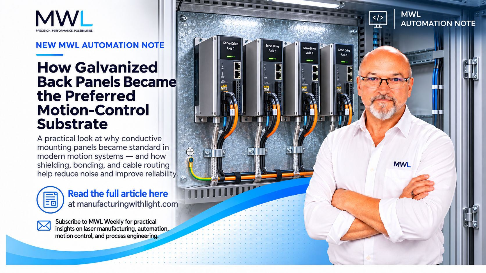
How Galvanized Back Panels Became the Preferred Motion-Control Substrate
MWL Automation Notes | Motion Control & Automation
Open almost any modern industrial motion-control cabinet, and you’ll likely find a galvanized steel mounting panel behind the drives, power supplies, controllers, and other components.
It might look like an ordinary sheet-metal panel, but it serves a much more important purpose than simply holding everything in place.
That metal panel is part of the machine’s electrical design.
From Painted Steel to Galvanized Panels
For many years, electrical control cabinets commonly used painted steel mounting panels. They were strong, inexpensive, and provided a convenient surface for mounting components.
As electronic controls became more sophisticated, particularly with the widespread adoption of variable-frequency drives and high-performance servo systems, a problem became increasingly important: electromagnetic interference (EMI).
Modern servo drives use high-speed electronic switching to control motor current. That switching generates high-frequency electrical noise that can interfere with encoder signals, communication networks, sensors, and other sensitive electronics.
Engineers needed more than a good protective ground. They needed a way to provide short, low-impedance paths for high-frequency noise currents.
Painted steel panels presented a problem.
Paint is an electrical insulator. Even though the steel underneath conducts electricity, a component mounted against the painted surface may not have a reliable electrical connection.
The traditional solution was to scrape away the paint wherever an electrical connection was required.
That worked, but it added labor, created inconsistent connections, and exposed steel that could eventually corrode.
Galvanized or zinc-plated steel offered a practical alternative.
The zinc coating provides corrosion protection while preserving an electrically conductive surface.
This allowed drives, filters, shield clamps, and other components to be mounted to a common conductive surface without removing paint at every intended bonding point.
No single year marked the start of galvanized panels as the industry standard. The industry adopted them gradually in response to the growing importance of electromagnetic compatibility, or EMC.
Rockwell Automation’s Servo Drive Installation Best Practices specifically recommends conductive-plated steel mounting panels for these reasons. [1]
Why the Panel Matters Electrically
A galvanized panel can act as a large, conductive bonding plane.
That’s important because electrical grounding behaves differently at high frequencies.
A conventional ground wire may be perfectly adequate for electrical safety, yet its inductance can make it a poor path for high-frequency currents.
A wide metal surface provides a much lower-impedance path for those currents.
This is especially important for servo systems, where rapid switching creates high-frequency currents that need a controlled return path.
By mounting drives and shield-termination hardware to a common conductive panel, engineers can reduce the likelihood of this noise reaching sensitive control circuits.
The panel must also be properly bonded to the cabinet and protective-earth system. It does not replace required protective-earth conductors.
Siemens and SEW-EURODRIVE both emphasize broad conductive mounting surfaces and short bonding connections in their EMC installation guidance. [2][3]
What About Servo Cable Shields?
This is where modern motion-control wiring can seem to contradict what many technicians were originally taught.
For years, a common rule was:
Ground a cable shield at only one end to prevent ground loops.
That rule still applies to certain low-frequency instrumentation and analog signal applications.
But high-frequency noise from modern servo drives presents a different problem.
A servo motor cable typically has a braided metallic shield surrounding its power conductors.
For many modern servo systems, manufacturers specify connecting this shield to the drive or conductive mounting structure at one end and the motor housing at the other.
And instead of twisting the shield into a small wire and connecting it to a ground terminal, the preferred method is often a 360-degree shield connection.
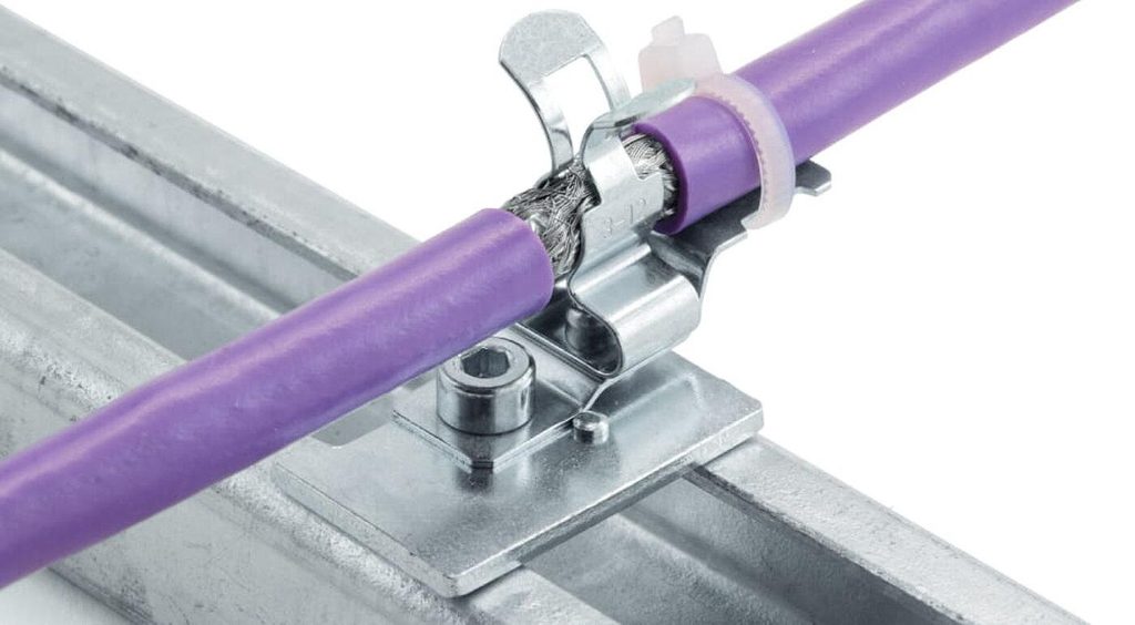
HEBOTEC: EMC cable shielding by HEBOTEC hebotec.de
A conductive clamp contacts the shield’s circumference and bonds it directly to the mounting plate or designated shield plate.
Why?
Because a long, thin ground wire can have considerable impedance at high frequencies, even when an ohmmeter indicates almost zero resistance.
A short, wide connection provides a better path for high-frequency currents.
This is one reason you will often see servo cable shields clamped directly to a galvanized mounting panel near the drive.
The shield connection at the motor is typically made through a metallic connector housing or EMC cable gland.
Always follow the drive and motor manufacturer’s termination instructions.
Cable Routing Is Just as Important
Good shielding cannot completely compensate for poor cable routing.
Servo motor power cables should generally be kept separate from encoder, feedback, communication, and low-level signal cables.
Running motor power and encoder cables alongside each other for several feet creates unnecessary opportunities for electrical noise to couple between them.
Where cables must cross, crossing at approximately 90 degrees reduces the length over which interference can occur.
Manufacturers provide separation requirements for their equipment. For example, Schneider Electric recommends at least 20 cm between certain motor and signal cables unless suitable shielding barriers are used. [4]
Why the Old Grounding Rules Aren’t Necessarily Wrong
The important distinction is between electrical safety grounding, low-frequency signal grounding, and high-frequency EMC bonding.
They serve different purposes.
The familiar single-point grounding approach can help prevent unwanted low-frequency currents from circulating through sensitive instrumentation.
High-frequency interference, however, is often better controlled using short, broad, multiple bonding connections.
That’s why modern servo installations frequently use both-end shield terminations and conductive mounting panels.
The two approaches are not necessarily contradictory. They address different electrical problems.
And not every cable shield should automatically be grounded at both ends. The appropriate method depends on the equipment, signal type, and installation.
The Takeaway
The galvanized back panel is a good example of how something that appears mechanically simple can become an important part of modern control-system design.
It provides a strong mounting surface, corrosion resistance, and, most importantly for motion systems, a practical way to establish reliable high-frequency electrical bonding.
Combined with proper cable shielding and routing, it helps prevent the intermittent faults and communication problems that can make servo systems so frustrating to troubleshoot.
A well-designed motion-control cabinet doesn’t just organize the components. It manages the electrical noise they create.
And understanding that is one of the first steps toward building and troubleshooting reliable motion systems.
References
[1] Rockwell Automation — Servo Drive Installation Best Practices
[2] Siemens — EMC Configuration Manual
[3] SEW-EURODRIVE — EMC in Drive Technology: EMC-Compliant Installation in Practice
[4] Schneider Electric — Electromagnetic Compatibility, EMC — Lexium Drives