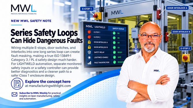
A concern for anyone automating or enclosing a LightWELD system
I have been thinking more about this as I consider taking LightWELD beyond handheld welding and into enclosed or automated systems.
Years ago, while working on a Class 1 laser machine containing Class 4 lasers, I learned that one of the harder parts of the design wasn’t the laser or motion system. It was making sure the machine safety system was as fault-tolerant as we thought.
That lesson is even more relevant today.
FACTS
1. A dual-channel safety relay does not automatically give you a Category 3 or PL d/e safety system.
ISO 13849-1 evaluates the complete safety-related control function. Architecture, component reliability, diagnostic coverage, common-cause failures, and other factors all contribute to the achieved Performance Level. The required PL must also come from the machine’s risk assessment. [1] ISO
In other words:
A Cat. 3-capable safety relay connected to a poorly designed input circuit does not make the entire machine Cat. 3.
2. Series-connected mechanical guard switches can create a recognized problem called fault masking.
ISO 14119 addresses guard interlocking, and ISO/TR 24119 specifically examined fault masking when multiple interlocking devices with potential-free contacts are connected in series to a single diagnostic unit. [2][3] ISO
This isn’t a theoretical edge case.
Manufacturers of safety equipment such as SICK and Schmersal document that fault masking in a series chain can reduce diagnostic coverage—and therefore reduce the Performance Level that the safety function can achieve. [4][5] SICK
THE PROBLEM
Imagine an enclosed LightWELD cell with:
Door 1, Door 2, an access panel, two E-stops, perhaps a fixture interlock, and other machine permissives.
A traditional design might put all those normally closed contacts into one long, dual-channel safety loop.
It looks safe. Open either door, and the laser shuts down. Push either E-stop and the machine stops.
But consider this example.
One contact in Door Switch 1 fails closed.
Later, somebody opens Door 2. Both safety channels open normally, so the safety relay sees what appears to be a perfectly valid safety demand.
Door 2 closes, the system is reset, and production continues.
Door 2 may have masked the failed contact on Door 1. The safety system can appear perfectly healthy during normal operation even though some of its redundancy has been lost.
That is the fault-masking problem ISO/TR 24119 was written to address. [3] ISO
And this is where older machine-safety habits can get us into trouble.
Twenty years ago, wiring every door and E-stop into a long series loop was very common. You still see it today because it is inexpensive, easy to understand, and appears to work when tested.
But “the machine stops when I open the door” is not the same as demonstrating diagnostic coverage and fault tolerance.
One important distinction
I wouldn’t say every series-connected safety circuit is automatically wrong.
Emergency-stop circuits need to be evaluated separately from guard interlocks. ISO 13850 covers the emergency-stop function, and even safety-system manufacturers note that multiple E-stops can sometimes be series-connected if the complete safety function still achieves its required Performance Level. [6][7] ISO
The real issue is blindly applying the same series-loop architecture to many frequently operated guard switches and safety devices without analyzing which faults it can hide.
SIMPLE SOLUTIONS
Fortunately, modern safety hardware makes this much easier than it used to be.
1. Give important safety devices their own inputs.
A configurable safety relay or small safety controller can monitor Door 1, Door 2, E-stops and other functions independently.
That improves diagnostics tremendously.
Instead of:
Something opened somewhere in the safety loop
the system can tell you:
Door 2 safety channel B failed to switch.
For a LightWELD production machine, better diagnostics also means dramatically easier troubleshooting.
2. Use modern electronic safety switches where appropriate.
Many current RFID/electronic guard switches use monitored semiconductor safety outputs, such as OSSD outputs, and are designed for safe cascading or series connection.
Unlike a string of ordinary dry contacts, each device can perform internal diagnostics. Some systems also provide device-level diagnostic information while maintaining the safety function. [4][5] SICK
3. Separate safety functions instead of creating one giant loop.
For example, an automated LightWELD cell might separately evaluate:
Emergency stop, enclosure doors, laser enable/interlock, hazardous motion, positioner or robot safety
The safety controller can then coordinate the required outputs while retaining diagnostic information about what actually caused the stop.
This is also where I think a programmable safety relay or small safety controller belongs in an MWL LightWELD controller architecture, rather than depending entirely on one traditional hardwired series chain.
4. Validate the safety function—not just the components.
ISO 13849-2 specifically addresses validation of the safety functions, category and Performance Level achieved by the complete safety-related control system. [8] ISO
A safety relay marked PL e is a component.
A machine achieving PL d or PL e is a system-level engineering result.
Why this matters for LightWELD
IPG already provides substantial safety functionality in LightWELD, including an E-stop, laser-delivery interlock, and provisions for door-switch interlock circuits. IPG also identifies LightWELD XR as a Class IV laser system. [9] IPG Photonics Corporation
But once we take that laser and put it into an automated machine, we have created a larger safety system.
The enclosure, doors, E-stops, motion, laser enable, and other hazards now have to work together.
And if the objective is a Class 1 laser machine containing a Class 4 laser, the protective housing and interlocking system are central to that design. OSHA describes exactly this arrangement: a high-power laser can operate as a Class I system when properly enclosed, labeled, and interlocked so hazardous laser radiation is not accessible during normal operation. [10] OSHA
That is why I would be cautious about simply taking an old safety schematic, adding a few more door switches to the series loop and calling the job finished.
Modern safety technology gives us better options.
And for anyone considering automating LightWELD or putting one into a Class 1 enclosure, I think this is an area worth looking at very carefully.
References
[1] ISO 13849-1:2023 — Safety of machinery — Safety-related parts of control systems — Part 1 ISO 13849-1:2023
[2] ISO 14119:2024 — Interlocking devices associated with guards ISO 14119:2024
[3] ISO/TR 24119:2015 — Evaluation of fault masking in serial connections of interlocking devices ISO/TR 24119:2015
[4] SICK — Safe Series Connection: Fault Masking and Diagnostic Coverage SICK Safe Series Connection technical information
[5] Schmersal — Safety in System / ISO 13849 and series-connected interlocks Schmersal Safety in System guide
[6] ISO 13850:2015 — Emergency stop function — Principles for design ISO 13850:2015
[7] Pilz — Series Connection of Emergency Stop Pushbuttons Pilz technical FAQ
[8] ISO 13849-2:2012 — Validation of safety-related control systems ISO 13849-2:2012
[9] IPG Photonics — LightWELD safety features and LightWELD XR information IPG LightWELD product information
[10] OSHA — Guidelines for Laser Safety and Hazard Assessment OSHA laser safety guidance
This is intended as general engineering discussion, not a complete machine-safety design. The required safety functions and Performance Levels should come from the risk assessment for the actual machine and be validated as a complete system.
#LaserSafety #LightWELD #MachineSafety #LaserWelding #FunctionalSafety #IndustrialAutomation #ManufacturingWithLight